Khun Tan Mountain Middle Railway Bridge
Introduction
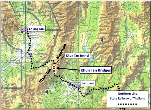
Khun Tan Mountain provided a substantial obstacle to extending the State Railway of Thailand’s Northern Line from Lampang to Chiang Mai. The solution included constructing three major bridges up the mountain’s eastern slope:1
The three bridges are:2
Stationing |
|||
Pang Lha, “Composite Bridge” |
E99°15.960 |
5 span: 15m+(3x30m) +15m=120m; photo (offsite link), looking south |
|
Pang Yang (S), “3-tower bridge” |
E99°15.990 |
4 span: 30m+60m +30m+22m=142m; photo (offsite link), looking north |
|
Pang Yang (N), “2-tower bridge” |
E99°15.950 |
3 span: 30m +60m+30m=120m; photo (offsite link), looking north |
(Note: Northern Line Railway Stationing increases from south to north)
The tan-colored line in the oblique view below traces the Northern Line of the State Railway of Thailand along the east side of Khun Tan Ridge, showing the locations of the three major bridges up to Khun Tan Tunnel. This page examines the middle bridge in more detail:3

The three bridges are well described in on-the-ground track-walking by members of ROTFAITHAI.COM. The texts are in Thai, but are fairly well translated if using Google Chrome as a browser. While the links are to relevant portions of their narrations, the first walk (Nakhonlampang) starts at the Composite Bridge and goes north, while the second walk (mirage_II) starts at the Khun Tan Tunnel and goes south:
By “Nakhonlampang”:
โฉบไปเที่ยวสะพานคอมโพสิต ตามติดด้วยสะพาน 3 หอ และ 2 หอ (offsite link) (2007, 8 pages)
(“Hovering over Composite, 3-towers, and 2-towers bridges”)
Coverage of the middle bridge begins at the top of page 5 with “Nakhonlampang” Post 10:16pm 12 Nov 2007, and completes farther down the page with four photos in Post 11:07pm 12 Nov 2007 (both links offsite).By “mirage II”:
ไปสัมผัสความสูงสุดเสียวของสะพานข้ามเหวขุนตานกัน (offsite link) (2013, 29 pages)
(“Let’s check the heights of the bridges on Khun Tan”)
For reasons not clear, almost all the photos that once accompanied mirage II’s post have apparently been deleted, but the Thai text is there, for those interested (view with Chrome browser to translate). Also, mirage II doesn’t use railway stationing nor coordinates to locate railway features which can be confusing.
The “3-Tower Bridge” actually has 4-towers
Nakhonlampang’s explanation (Posts of 12/11/2007 10:12 pm and 12/11/2007 10:16 pm) may be somewhat confusing per Chrome’s translation. Paraphrasing that translation: the structure, two cantilever deck trusses connected with a plate girder, and a simple deck truss extension at the north end, was originally designed to handle 10.5 ton axle loadings and was erected in 1915 with three supporting towers. Viewed from the east (with the mountain as a backdrop as in the drone video), schematically the bridge looked like this:4
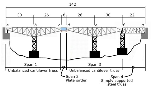
The cantilevered deck spans, 1 and 3, are mirror images, with lengths ab and de four meters longer than lengths bc and de (respectively). Spans 1 and 3 are firmly anchored at points a and f to counteract potential concentrated loading between Points b and e. At point a, steel members are embedded in the concrete abutment. At point f, the tower would have been designed to handle both the gravity loading of a train and the uplift from a concentrated loading between Points b and e (no photo was found detailing the connections between Truss def, Point f tower, and the foundation for the tower).
Single span, cd (in blue/gray), connecting the two cantilever trusses, is a built-up riveted plate girder with web stiffeners presumably pin connected at one end with a roller bearing at the other end, in order to deal with thermal expansion / contraction of the structure from a to f.
To allow the bridge to handle an increased specification of 15 ton axle loadings, a fourth tower was added in 1967 (as shown in red below at cd), along with considerable supplemental bracing to the original structure, plus the simple deck truss fg was replaced by a welded plate girder (in blue):5

Hence, the so-called “3-tower” bridge now has four towers.
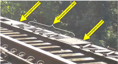
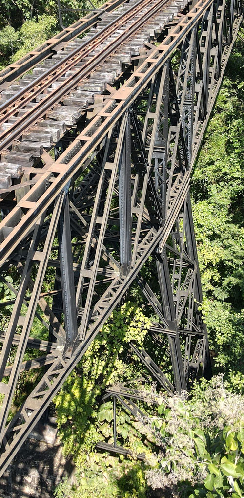
If the rotfaithai links above are followed, this is the structure that was examined in 2007 and 2013, some 40+ years after the structure was strengthened. To differentiate old from added structure, there are general rules of thumb: one, the original steel structure was riveted throughout, whether shop fabricated or field-erected, while, two, the added members plus reinforced existing ones were connected with nuts and bolts; sometimes supplemental members appear to have been shop welded, a process not used in 1915 (some of the photos below reference points in the schematic above).
Here is an example of diagonal lacing, both original and added to an existing girder:6
Some simple assemblies were shop fabricated and transported to site. For example, the horizontal members and cross-bracing of the new tower, at cd, appear to have been welded which would have been a shop function. The members were then transported to site and bolted in place:7

Other views possibly of interest:
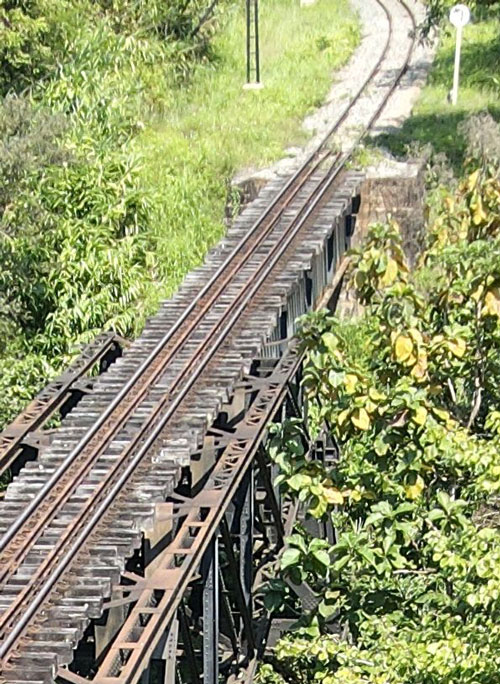
South end of bridge (Point a) at abutment:8
South Tower (one of original towers, at Point b):9

Added tower (Points c and d):10
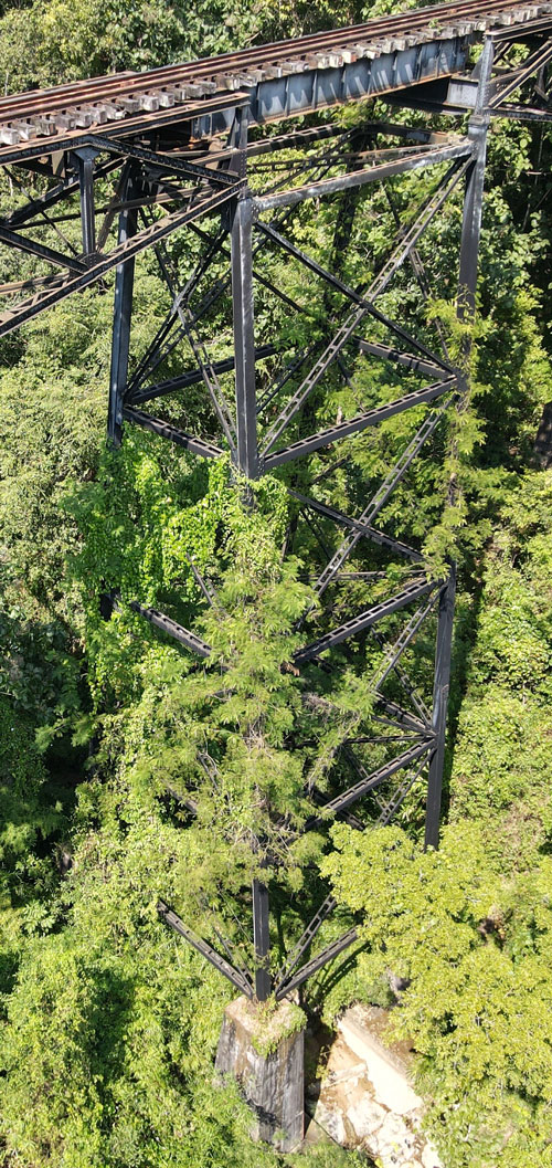
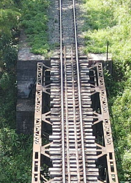
Additional views of the 8-meter span, cd. Not very accessible from the ground, or from the bridge itself, the span was viewed close-up with the use of a drone:11

Close-ups of end points, c and d:12

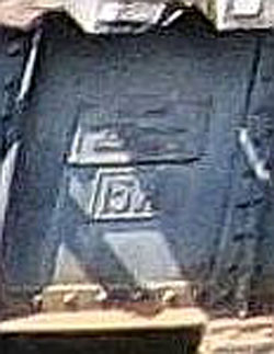
The built-up plate girders are actually 9.2-meters long13 — 1.2-meters longer that the nominal span of 8-meters — to allow an overlap with the cantilevered trusses, which, if evenly spaced, would be 60 cm on either side. Included in that overlap would be 7 cm, the maximum thermal expansion.14 Note the 15 ton capacity of the beam is clearly visible:15
Northerly Tower (one of the original towers, at Point e):16
The Northern-most Tower (again, one of the originals, at Point f) and north abutment (Point g):17
A special thanks to “Charlie F.O” for the drone work that allowed a close-up examination of the bridge.
| 2023 09 04 | First published on Internet | |
| 2024 Feb 29 | Converted to WordPress by Ally Taylor | |
| 2025 May 11 | Updated, author errors & typos corrected | |
Last Updated on 15 October 2025
- Extract from Tactical Pilot Chart TPC J-10C, Burma, Laos, Thailand, Edition 4 (1983). Markup by author using Microsoft Publisher. [Ref: \02370 Lampang\ Railroad\ Khun Tan bridges\ Presentations\ 0 Bridges. grouped\ CNX-LPG RR Map.jpg].[↩]
- Table is based on bridge stationing and span counts listed in BR Whyte, The Railway Atlas of Thailand, Laos and Cambodia (Bangkok: White Lotus, 2010), p 28 and coordinates and lengths from Google Earth. Photos reference Rotfaithai Gallery collection.[↩]
- Google Earth: oblique view (elevation exaggeration = 2) looking approximately north. Markup by author using Microsoft Publisher. [Ref: \02370 Lampang\ Railroad\ Khun Tan bridges \Presentations\ 0 Bridges. grouped\ CNX-LPG RR Map Br 2.jpg].[↩]
- Adapted from Nakhonlampang’s schematic: Original bridge, by author using Microsoft Publisher.[↩]
- Adapted from Nakhonlampang’s schematic: Reinforced bridge, by author using Microsoft Publisher.[↩]
- Part DSCF2473.jpg of 02 Dec 2014; annotated by author using Microsoft Publisher. Note: this photo is actually of a detail on the North Bridge (Sta 678+324) similar to that on the Middle Bridge. [Ref: \02370 Lampang\ Railroad\ Khun Tan bridges\ Photos-Hak & KhunTan Sta\ 3 North br\].[↩]
- Part of 20221025105818_photo.jpg by Charlie F.O, drone pilot, with markup by author using Microsoft Publisher. [Ref: \02370 Lampang\ Railroad\ Khun Tan bridges\ _pub files\ 2-tower fasteners.jpg].[↩]
- Part of 20221025105914_photo.jpg by Charlie F.O, drone pilot. [Ref: \02370 Lampang\ Railroad\Khun Tan bridges\ KHUN TRESTLE BRIDGE\ Khun Trestle Bridge Photography 25-10-2022\ Extracts\D-South abutmt-alt.jpg].[↩]
- Part of 2022102511220_photo by Charlie F.O, drone pilot. [Ref: \02370 Lampang\ Railroad\ Khun Tan bridges\ KHUN TRESTLE BRIDGE\ Khun Trestle Bridge Photography 25-10-2022\ Extracts\F-South tower-alt.jpg].[↩]
- Part of 2022102511316_photo.jpg by Charlie F.O, drone pilot. [Ref: \02370 Lampang\ Railroad\ Khun Tan bridges\ KHUN TRESTLE BRIDGE\ Khun Trestle Bridge Photography 25-10-2022\ Extracts\G2-mid tower top-obl.jpg].[↩]
- Part of 2022102511250_photo.jpg by Charlie F.O, drone pilot. [Ref: \02370 Lampang\ Railroad\ Khun Tan bridges\ KHUN TRESTLE BRIDGE\ Khun Trestle Bridge Photography 25-10-2022\Extracts\ G1-mid tower top.jpg].[↩]
- Ibid.[↩]
- Nakhonlampang Post 12/11/2007 10:12 pm.[↩]
- Calculation from The Engineering Toolbox:
Range of thermal expansion:
dl = L α (t1 – t0)
dl = change in object length
L = initial length of object
a = linear expansion coefficient
t0 = initial temperature
t1 = final temperature
dl = L α (t1 – t0)
= 120m x 0.0000117 x 50
= 0.07m = 7 cm(In other words, the increase in length of a 120 m structure made of Spec A36 steel because of a change in temperature of 50 degrees C would be 7 cm.).[↩]
- Part of 2022102511250_photo.jpg by Charlie F.O, drone pilot.[↩]
- Part of 202210251148_photo.jpg by Charlie F.O, drone pilot. [Ref: \02370 Lampang\ Railroad\ Khun Tan bridges\ KHUN TRESTLE BRIDGE\ Khun Trestle Bridge Photography 25-10-2022\ Extracts\I-North tower.jpg.[↩]
- Part of 2022102511426_photo by Charlie F.O, drone pilot. [Ref: \02370 Lampang\ Railroad\ Khun Tan bridges\ KHUN TRESTLE BRIDGE\ Khun Trestle Bridge Photography 25-10-2022\ Extracts\H-North abutmt.jpg].[↩]